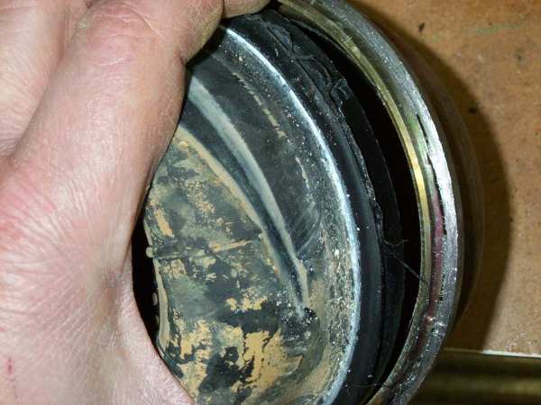
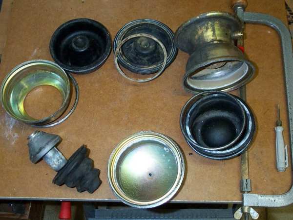
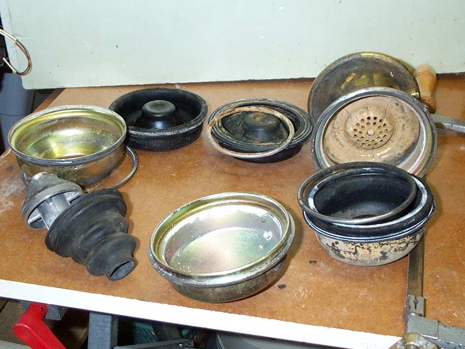
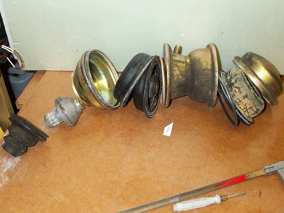
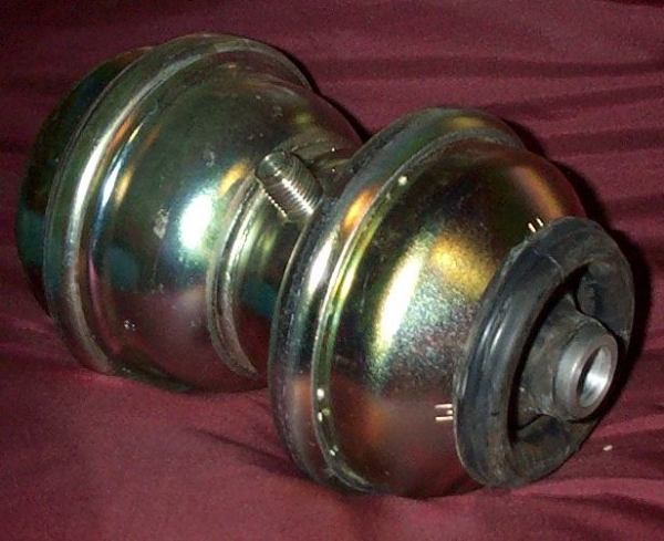
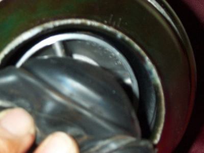
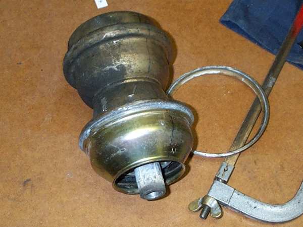
- dust cover (rubber)
- piston, aluminum alloy (press stud to the diaphragma
!!)
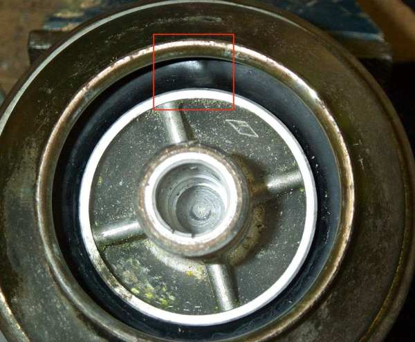
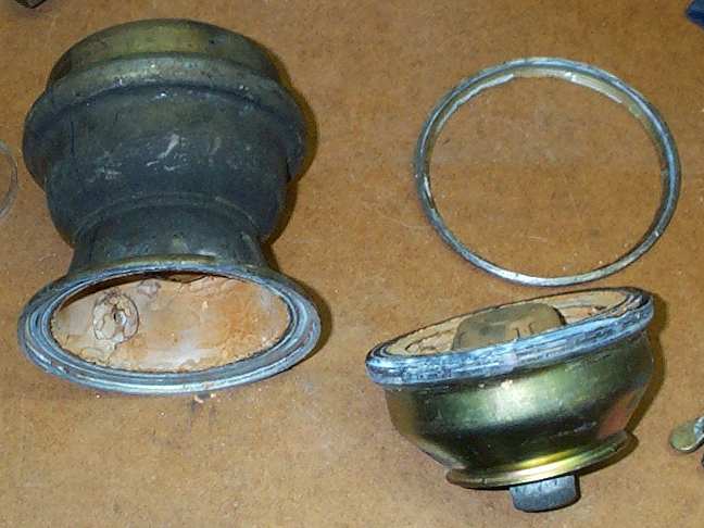
- lower cap (mild steal pressed hose)
- seal rubber diaphragma (thin rubber attached to armed
diaphragma)
- press ring (forms thin rubber diaphragma)
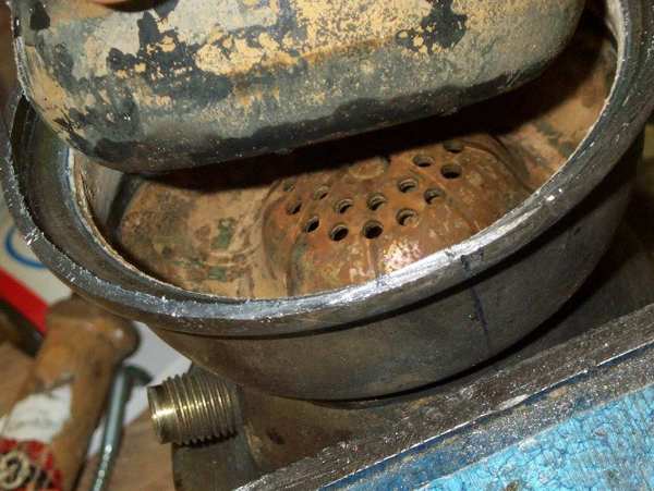
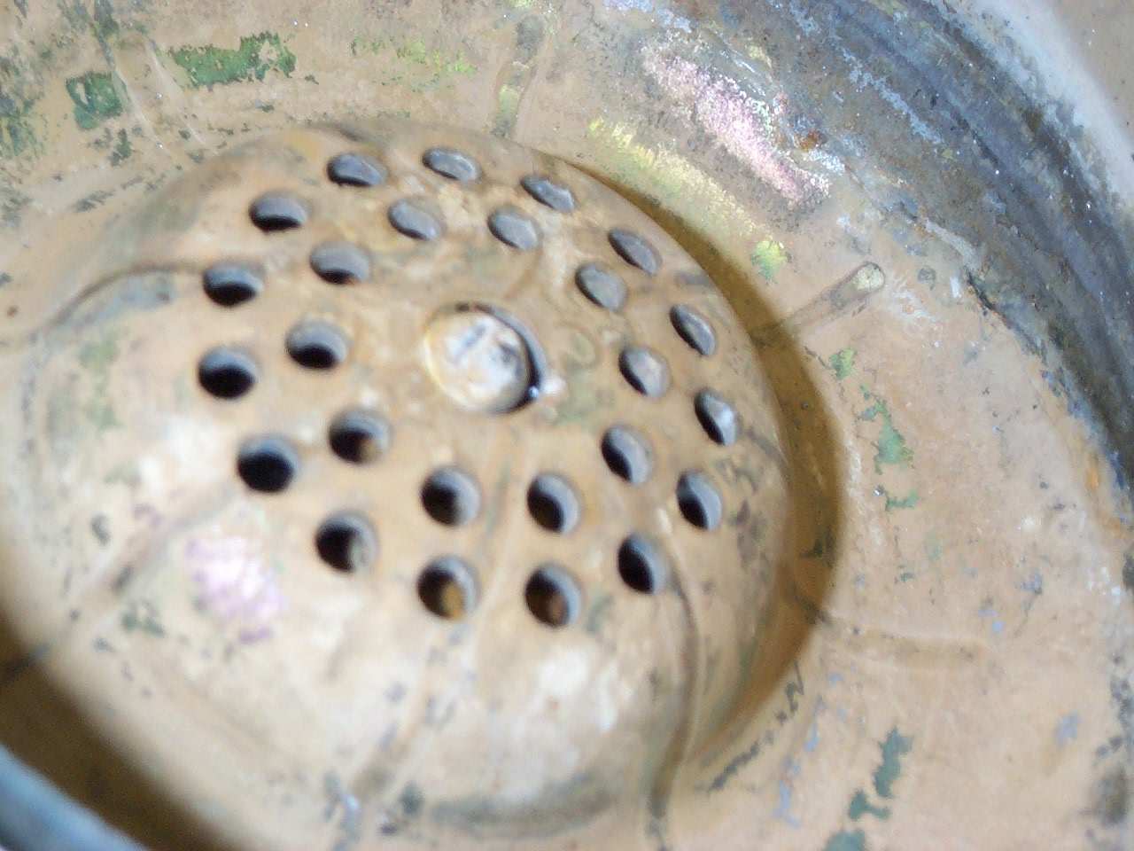
- steal mesh armed diaphragma (What a crap quality !!!)
:(
- body with valves (to investigate)
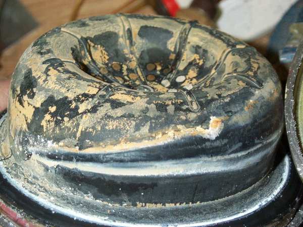
- upper diaphragma (simple rubber)
- press ring (forms upper diaphragma)
- upper cap
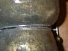

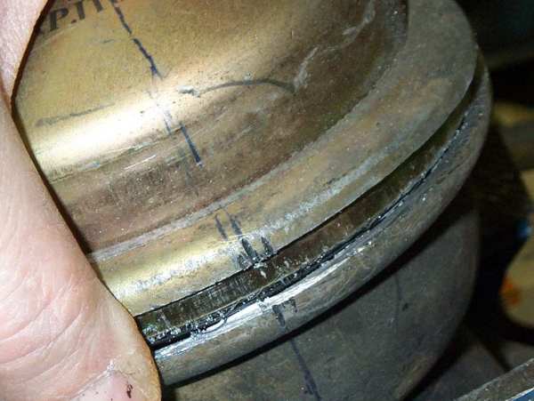
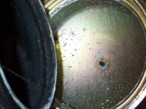
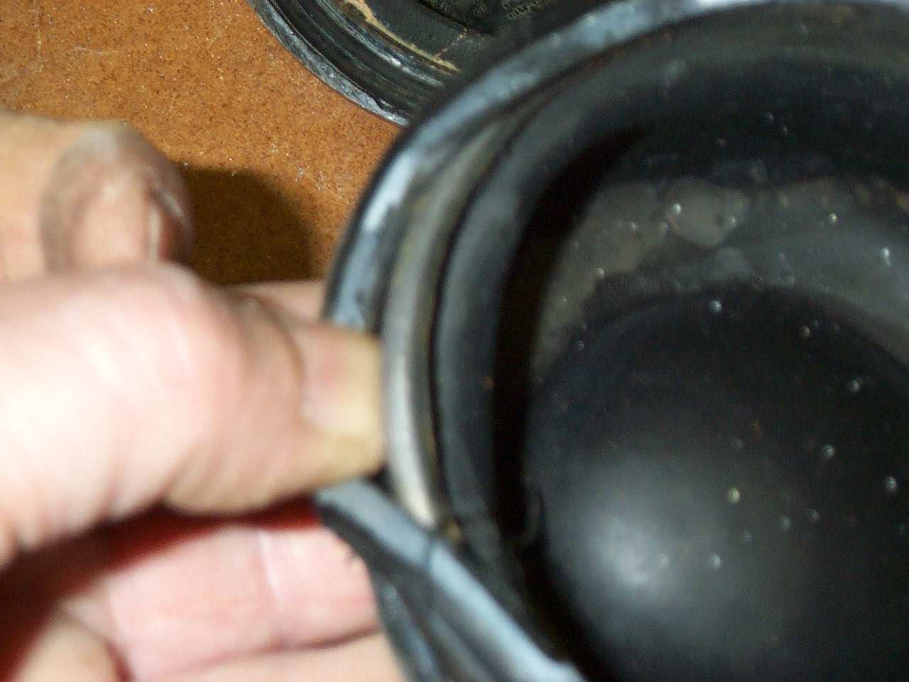
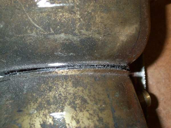
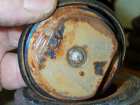
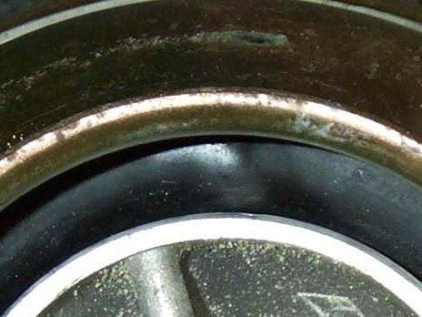
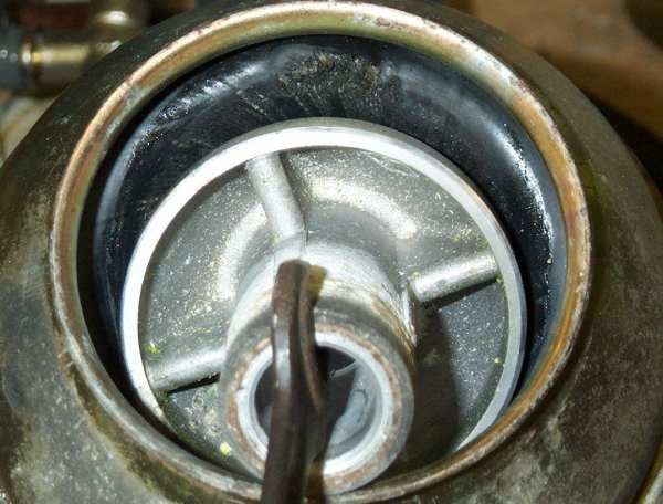
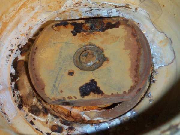
Cut around the weld line, the non-return valve system
of MGF rear or Metro rear displacer. Again, very rusty steel parts.
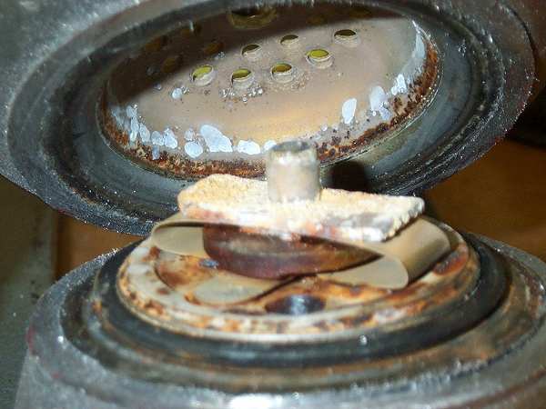
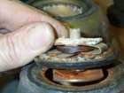
 Nitrogen
sphere side
Nitrogen
sphere side 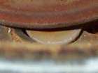 one
valve, spring slipped a little bit to the right hand side
one
valve, spring slipped a little bit to the right hand side
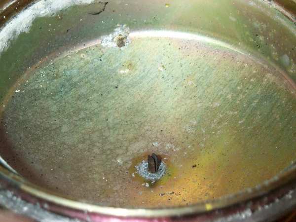
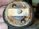
 fluid
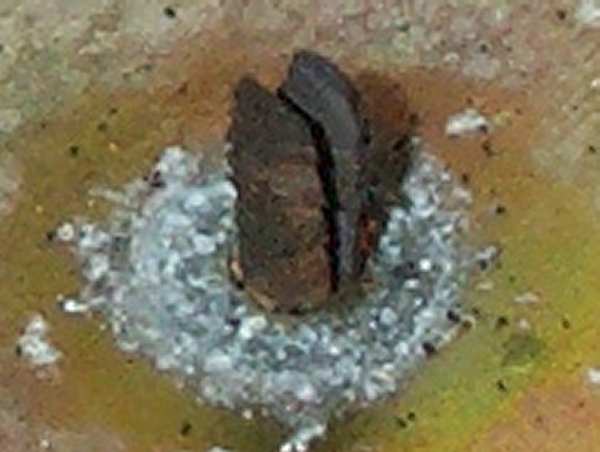
sphere side (in the center is located a long rivet)
fluid
sphere side (in the center is located a long rivet)
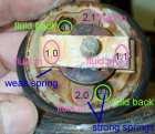
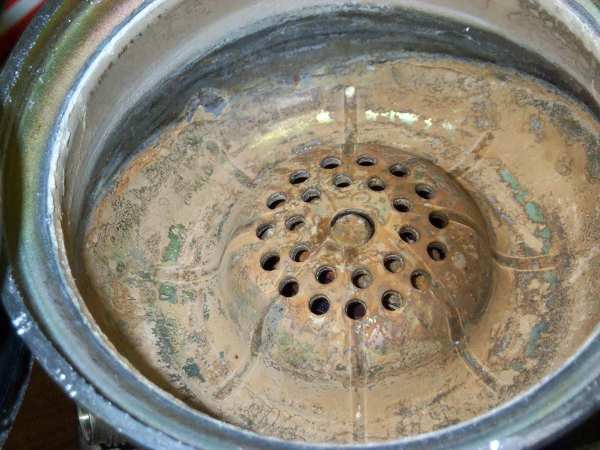
4 valves for back flow
1.0/1.1 weak spring, large diameter
2.0/2.1 strong spring small diameter
2 valves for fluid flow to the nitrogen pressure sphere
3.0/3.1 equal spring and diameter as No 2.0/2.1
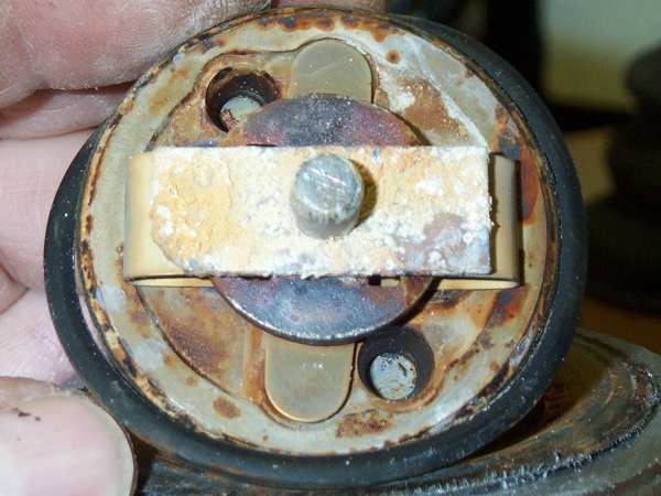
Drawings of the spring and valve system follow. First
impression:
There are for each non return and damp accessing holes in the block. Closed
by metal leave springs. The upper bended spring is surely weaker than
the lower single leave. Springs have both functions. The damping of flow
and transport of force to keep the holes closed.
The valve block is sealed at its outer diameter by a O-Ring
against the upper and lower sphere cap.


 valve
block ... shouldn't the fluid content a rust protection component???
valve
block ... shouldn't the fluid content a rust protection component???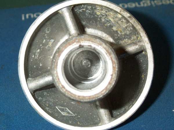 piston
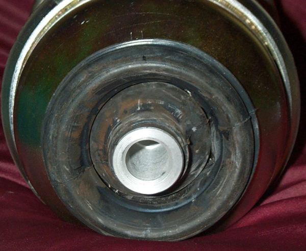
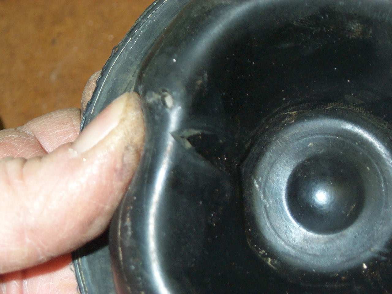
hole for the knuckles shaft
piston
hole for the knuckles shaft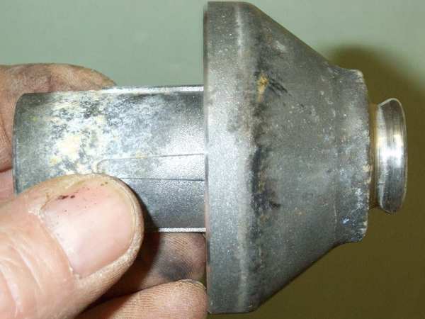 piston
stud
piston
stud 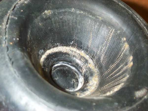 piston
stud clamp in lower diaphragma
piston
stud clamp in lower diaphragma