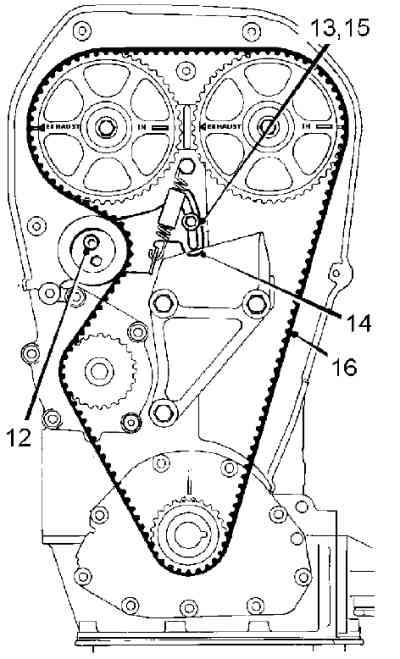
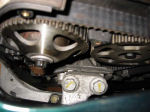
Manual tensioner with spring, used to be used at MGF
belt OE Ref GTB1238/CDU2749& tensioner OE Ref CDU3558.
The QH part number is QBK219
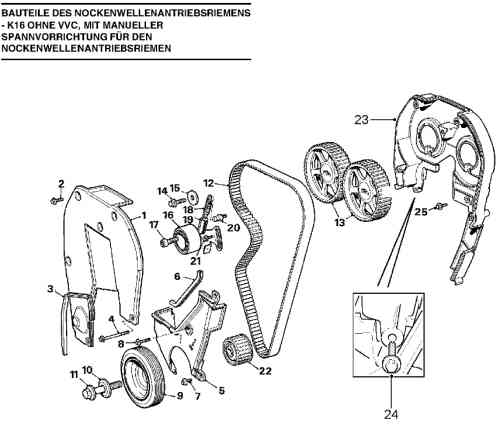
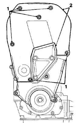
1 Vordere Abdeckung oben LJR104000 Cover assembly-upper front timing
belt 11 GBP
2 M6 Schraube Abdeckung oben
3 Dichtung Abdeckung oben
4 M6x90 Schraube Abdeckung oben und unten
5 Abdeckung unten vorn LJR104350 Cover-lower front timing belt 7GBP
6 Dichtung Abdeckung unten
7 M6 Schraube Abdeckung unten
8 M6x16 Schraube Abdeckung unten
9 Kurbelwellenscheibe
10 Sonderscheibe Riemenscheibenschraube
11 Schraube Kurbelwellenscheibe 22mm, Scheibe, alte Nr. LHB10050 / 24,5mm
neu LHH100480 / 28 mm
12 Nockenwellenantriebsriemen (old version HR70264 X 23MM neu 26mm)·
13 Nockenwellenräder
14 Nockenwellenradschraube
15 flache Scheibe
16 Spannriemenscheibe und Grundplatte (LHG000010 ??? statt alt: LHG100480)
17 Inbusschraube Riemenscheibe
18 Spannscheibenfeder
19 Federhülse
20 Stützschraube
21 Flanschkopfschraube Spannergrundplatte
22 Kurbelwellenrad
23 Abdeckung hinten LJR104320 Cover assembly-upper rear timing cover 8GBP
24 Schraube Abdeckung hinten an Kühlmittelpumpe
25 Schraube Abdeckung hinten
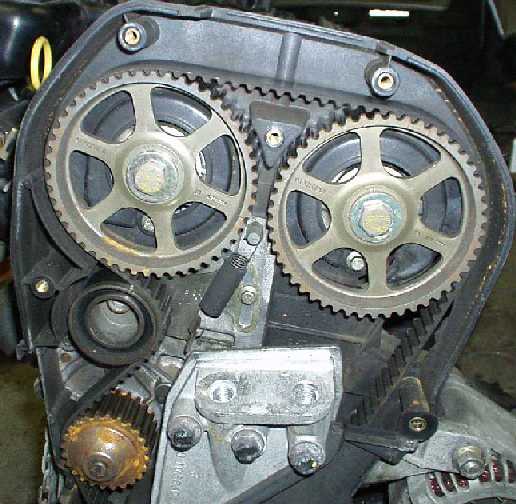
Manual tensioner
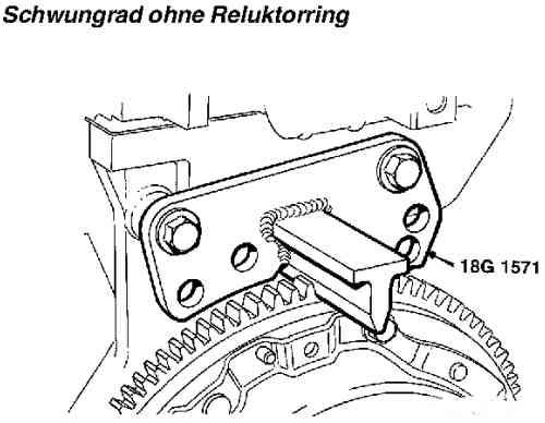
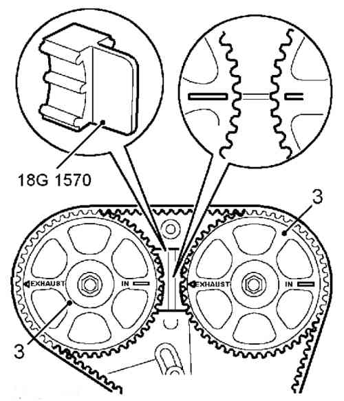
cam locking tool 18G1570
#3
old No WAM3114 Pulley-timing belt driven
until VIN ??1466?? Engine No 18K4FJ31 274137 and 18K4FJ32 278811
new LHB101360 Pulley-timing belt driven
GoMy old cambelts (VVC) looked like new BUT the alternator belt seems to be of dubious quality. Hundreds of small cracks in the ribbed inner material,hard to notice as the outside of the belt looks fine.
Roger P. has a very useful remark in his write-up on how to change the headgasket. By sligthly move the crank just a few degrees anti-clockwise when refitting the new belt it comes spot on. With the indication marks totally lined up at the crank it can be very difficult to get the belt on!
As the Atlas camshaft bolts are kown to shear I changed them for Mikes "Lifesavers". Can be done without disturbing the installed belt according to supplied instruction. / Carl.
Dave Smyth wrote (MG Cars BBS)
Used a hydraulic jack under back offside axle. Engine side cover Torx20
top right, plus two plastic pins below. Used a screwdriver to cut head
then push center through. The outer pin will then be able to be pulled
out.
Used a seperate jack under sump.
The idler allen key can be accessed from above & below top. I found
ideal to loosen & tighten from above.
Withdrawing allen bolt to replace will not cause it to fall away.
My belt had a spring tensioner.
Accessed from above just below center cam spockets. To move this to take
of the tension was tricky, access from below thorough a narrow gap between
body / axle
8mm nut access is restricted. The engine mount gets in the way, the tool
needs to be a miniture spanner.
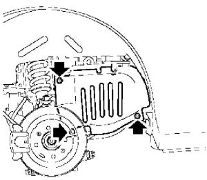
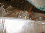
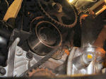
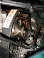
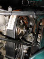
Photos, courtesy Dave Smyth 2005
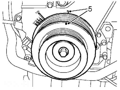
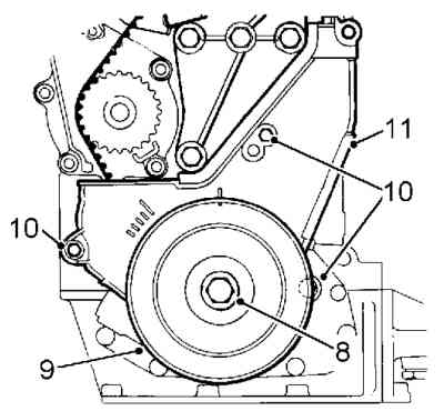
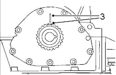
#3 lower wheel at the crank shaft measures changed at early MGF
#12 22mm to 205 Nm
WAM4243 Bolt-crankshaft pulley
LYF10051 Washer
Crankshaft pulley
until VIN ??1466?? Engine No 18K4FJ31 274137 and 18K4FJ32 278811
, old crankshaft Pulley No. LHB10050 width 24,5mm
new No. is LHG100500 with width 28 mm ??
crankshaft pulley gear
No. LHH100480
(found by Axel G. )
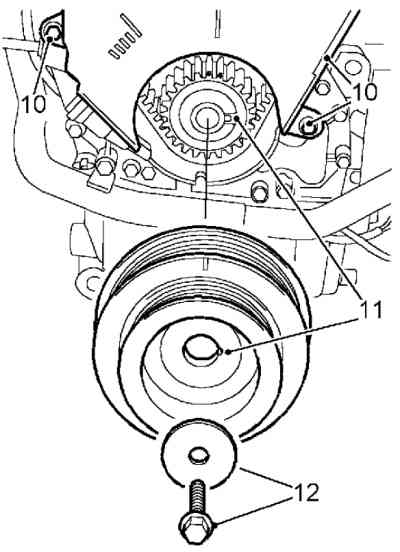
KURBELWELLENSCHEIBE - BEI SCHALTGETRIEBE
Servicereparatur Nr. - 12.21.01
Ausbau
1. Massekabel der Batterie abklemmen.
2. Fahrzeug hinten anheben.
WARNUNG: Arbeiten Sie nicht unter dem Fahrzeug, wenn es nur durch einen
Wagenheber abgestützt ist. Setzen Sie das Fahrzeug immer auf Montageständern
ab.
3. Laufrad abbauen.
4. Generatorantriebsriemen entfernen. Siehe ELEKTRISCHE ANLAGE, Reparaturen.
5. Starter entfernen. Siehe ELEKTRISCHE ANLAGE, Reparaturen.
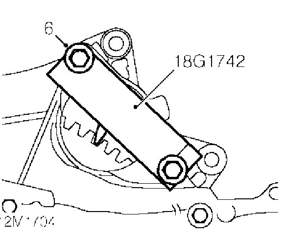
6. Kurbelwelle mit Hilfe von Werkzeug 18G1742 blockieren.
7. Schraube zur Befestigung der Kurbelwellenscheibe entfernen und Unterlegscheibe
aufnehmen.
8. Kurbelwellenscheibe entfernen.
Einbau
1. Auflageflächen von Kurbelwelle und Riemenscheibe säubern.
2. Kurbelwellenscheibe an Kurbelwelle anbringen und sicherstellen, dass
die Kerbe an der Riemenscheibe über der Nase am Zahnrad sitzt.
3. Schraube und Unterlegscheibe zur Befestigung der Kurbelwellenscheibe
an der Kurbelwelle montieren und mit 205 Nm festziehen.
4. Kurbelwellensperre 18G1742 entfernen.
5. Starter montieren. Siehe ELEKTRISCHE ANLAGE, Reparaturen.
6. Hilfsantriebsriemen montieren. Siehe ELEKTRISCHE ANLAGE, Reparaturen.
7. Laufrad/Laufräder montieren, Radmuttern montieren und über
Kreuz mit 90 Nm festziehen.
8. Montageständer entfernen und Fahrzeug senken.
9. Massekabel der Batterie anschließen.
LAGERUNG - RECHTS - ALLE MODELLE
Ausbau
1. Massekabel der Batterie abklemmen.
2. Motorraumgrill entfernen. Siehe KAROSSERIE, Außenteile.
3. Motorraumabschirmung entfernen. Nähere Angaben in dieser Sektion.
4. Fahrzeug hinten anheben und auf Montageständer(n) absetzen.
WARNUNG: Arbeiten Sie nicht unter dem Fahrzeug, wenn es nur durch einen
Wagenheber abgestützt ist. Setzen Sie das Fahrzeug immer auf Montageständern
ab.
5. Laufrad hinten rechts abbauen.
6. Befestigungselemente der Abdeckung entfernen und Abdeckung entfernen.
7. Längslenker entfernen. Siehe AUFHÄNGUNG HINTEN, Reparaturen.
8. Ein Stück Holz auf den Werkstattheber legen und Motor mit dem
Werkstattheber abstützen.
MOTOR
9. Mutter und Schraube zur Befestigung der Motorberuhigungsstrebe am Widerlager
rechts entfernen.
10. Mutter zur Befestigung des Motorhalters oben an Motor-Hydramount rechts
lockern.
11. 2 Schrauben zur Befestigung des Halters oben am Motor entfernen.
12. 4 Schrauben zur Befestigung des Widerlagers rechts am Hilfsrahmen
entfernen.
13. Motor mit dem Werkstattheber weit genug anheben und Widerlager rechts
mitsamt Motorlagerung aus dem Fahrzeug manövrieren.
HINWEIS: Nicht weiter zerlegen, wenn das Bauteil nur zur Erleichterung
des Zugangs entfernt wird.
14. 2 Schrauben zur Befestigung des Hydramounts am Widerlager entfernen,
Halteband aufnehmen und Hydramount entfernen.
15. Mutter und Halterbefestigung oben von Hydramount entfernen.
Einbau
1. Hydramount und Auflagefläche am Widerlager säubern.
2. Halterbefestigung oben an Hydramount anbringen, Mutter montieren, aber
noch nicht festziehen.
3. Hydramount und Halteschlaufe an Widerlager anbringen. Schrauben montieren
und mit 45 Nm festziehen.
4. Motorberuhigungsstrebe an Widerlager anbringen, Mutter und Schraube
montieren, aber noch nicht festziehen.
5. Widerlagergruppe an Hilfsrahmen anbringen und in Einbaulage manövrieren.
6. Mit Unterstützung eines Helfers Motor in Position bringen und
Halter oben an Motor ausrichten, Schrauben montieren, aber noch nicht
festziehen.
7. Motor mit dem Werkstattheber absenken, Widerlager an Schraubenlöchern
ausrichten.
Schrauben zur Befestigung des Widerlagers am Hilfsrahmen montieren und
mit 45 Nm festziehen.
8. Schrauben zur Befestigung des Halters oben am Motor mit 100 Nm festziehen.
9. Mutter zur Befestigung des Halters oben am Hydramount mit 82 Nm festziehen.
10. Mutter und Schraube zur Befestigung der Motorberuhigungsstrebe am
Widerlager mit 85 Nm festziehen.
11. Werkstattheber unter dem Motor entfernen.
12. Längslenker montieren. Siehe AUFHÄNGUNG HINTEN, Reparaturen.
13. Abdeckung anbringen und befestigen.
14. Laufrad/Laufräder montieren, Radmuttern montieren und über
Kreuz mit 90 Nm festziehen.
15. Montageständer entfernen und Fahrzeug senken.
16. Motorraumabschirmung montieren. Nähere Angaben in dieser Sektion.
17. Motorraumgrill montieren. Siehe KAROSSERIE, Außenteile.
18. Massekabel der Batterie anschließen.
From: Kes Kidderminster kes@kcall.co.uk on 19 September 2002 at 21:11:42
(UK time)
Hi,
Dave, I've seen a DIY electric impact wrench for about £25, if I remember rightly. I don't know if you can hire these (you may even be able to hire an compressor and air impact wrench, but some hire firms are scary about the maintenance on compressors). Whether an electric impact wrench is man enough for the job is another thing. If it gets the pully off then after you've used it to refit and tighten the pulley you could get your garage to check the tightness with their kit. Perhaps a mobile mechanic with a compressor could crack and retighten the pulley nut for a few notes.
Don't, by the way, fit the camshaft locking tool until the crankshaft pulley is loosened (does that sound obvious?). Loosen the pulley bolt a little, line up the pulley mark, check that the cam sprockets are aligned, fit the camshaft locking tool, take off the crankshaft pulley, then swap the belt Don't turn the crankshaft AT ALL! There must be absolutely no slack on the drive side of the new belt between the crankshaft pulley and the exhaust cam sprocket (that's obvious too). Check that the pulley mark is correct (the cam sprockets will of course be correct). Just hand-tighten the pulley bolt, take the slack out of the belt with the tensioner, remove the cam locking tool, and tension the belt as per the manual. Tighten the pulley bolt with whatever means you loosened it.
I think that's it. If I've made any glaring errors someone will correct me. Good luck, just don't hurry, and check those cam/pulley marks again!
Regards, Kes.
--------------------------------------------------------------------------------
From: mike on 20 September 2002 at 19:33:21 (UK time)
Good advice there Kes, just a thought, the main engine mount bolts have
to be removed, be careful here as the engine needs support and if it moves
can tighten up the bolts on removal taking the threads out of the mount
as well,if this happens a new engine mount will be required:-(
tim woolcott, Dulwich, London Posted 18 May 2005 at 23:03:25
UK time
As Rob has already mentioned, I had to replace my water pump a couple
of months ago and it's not rockt science just bloody awkward. A lot has
to be done by sense of smell since you can't see a great deal.
A few things to consider:
Cam Belt removal
The hardest bit of the cam belt removal is getting the Enginge Mount bolt
removed. A large breaker bar or impact wrench is essential.
Make sure you set the cams with the markers on the pulleys facing each other. Also put a reference mark on the crank pulley (the timing notch is on the BACK flange of the crank pulley don't be confused by the one on the front flange!)
You will need to use the breaker bar to undo the hex bolt holding the tensioner and a cranked 8mm ring spanner to remove the slider bolt.
Water Pump and pipes
All straight forward except remember the bolt at '10 O'clock on the water
pump flange is removed from the opposite side.
The rubber hoses will be a bit of a pain to remove from the metal coolant pipes, be careful not to damage the rubber pipes.
Re-fitting the cam belt.
Leave the car in gear when re-fitting, you don't want to turn the crank!!!
Make sure you have enough tension on the 'driven side' of the belt (nearest
the bukhead. Get the belt onto the exhaust pulley first, only push it
on by 5mm or so.
It is likely that the cams have forced the pulleys apart a little, you
need to ensure that the belt is not too slack (take note how tight the
original belt was) It may be necessary to rotate the two cams towards
each other with 17mm spanners (WITH CAM LOCKING TOOL IN PLACE)this can
give you that important half tooth to get the belt on the inlet pulley.
Now just the waterpump and tensioner. From experience I have found that it is easier to place the belt around the waterpump and then fit the big tensioner bolt (if you fit the big bolt before getting the belt around the tensioner you'll make your life a lot harder) you can just about see what you're doing if you bend the metal wheel panel into the wheel arch (bend it back again afterwards.
Setting the tension is fun. use a LONG screw driver to push the slider up and use the 8mm setting bolt to hold it whilst doing up the big hex bolt with the breaker bar.
Bleeding coolant.
ensure you bleed ALL of the 3 main bleed points I found I had to apply
a little air pressure to the expansion tank to bleed the engine bay point
correctly.
Do a 'sanity check' and make sure there is nothing loose in the engine bay. REMOVE the cam locking tool and start the engine if you hear 'chirping' the tensioner is too tight, adjust it and try again. (Note: don't re-assemble every just yet incase you need to re-adjust.)
Sorry I can't help with the other VVC belt, I haven't done this before (shouldn't be too tricky if you can do the main belt).
Don't expect to do all of this in one day, it may be possible if you have done it before but not as a novice. It's not worth rushing.
These are not full and comprehensive notes but highlight a few of the main points you'll come across.
Good luck
Tim
Ausbau
VORSICHT: Nach dem Abbau eines Zylinderkopfes oder dem Austausch von Nockenwellenantriebsrädern müssen immer die Nockenwellenantriebsriemen erneuert werden.
Nockenwellenantriebsriemen müssen vorsichtig gelagert und gehandhabt werden.
Nockenwellenantriebsriemen immer flach ablegen und nie stärker als 50 mm biegen.
Ein verdrehter oder zu stark gebogener Nockenwellenantriebsriemen darf nicht weiterverwendet werden, da die Faserverstärkung dadurch beschädigt worden sein kann.
Nockenwellenantriebsriemen dürfen nicht weiterverwendet werden, wenn vom Abriebstaub abgesehen Schmutz oder Fremdkörper unter ihrer Abdeckung vorhanden waren.
Nockenwellenantriebsriemen dürfen nicht weiterverwendet werden, wenn Kolbenfresser aufgetreten sind. Nockenwellenantriebsriemen, die mehr als 77.000 km hinter sich haben, dürfen nicht weiterverwendet werden. Ölverschmutzte Nockenwellenantriebsriemen nicht verwenden. Die Ursache der Verschmutzung MUSS behoben werden.
1. Massekabel der Batterie abklemmen.
2. Fahrzeug hinten anheben und auf Montageständer(n) absetzen.
WARNUNG: Arbeiten Sie nicht unter dem Fahrzeug, wenn es nur durch einen
Wagenheber abgestützt ist. Setzen Sie das Fahrzeug immer auf Montageständern ab.
3. Laufrad hinten rechts abbauen.
4. Motor-Hydramount rechts entfernen. Nähere Angaben in dieser Sektion.
5. 5 Schrauben zur Befestigung der oberen Abdeckung des Nockenwellenantriebsriemens
an der Abdeckung hinten entfernen.
6. Untere Schraube zur Befestigung der oberen Abdeckung des Antriebsriemens
lockern, Abdeckung entfernen und Dichtung aufnehmen.
7. Einen verlängerten Steckschlüssel an der Kurbelwellenscheibenschraube
ansetzen und Kurbelwelle im Uhrzeigersinn drehen, um die Nockenwellenradmarken
auszurichten - 90° vor OT.
Nockenwellensperre 18G1570 zwischen die Nockenwellenräder montieren.
VORSICHT: Die Kurbelwelle nie mit Hilfe des Nockenwellenrads, dessen Befestigungsschrauben
oder des Nockenwellenantriebsriemens drehen.
8. Darauf achten, dass die Einstellmarke an der Kurbelwellenscheibe auf
die Marke an der Antriebsriemenabdeckung unten ausgerichtet ist.
9. Bei Weiterverwendung des Nockenwellenantriebsriemens die Laufrichtung
am Riemen markieren.
10. Kurbelwellenscheibe entfernen. Nähere Angaben in dieser Sektion.
11. 3 Schrauben zur Befestigung der unteren Abdeckung des Nockenwellenantriebsriemens
am Zylinderblock entfernen, Abdeckung und Gummidichtung entfernen.
12. Schraube von Nockenwellenantriebsriemenspanner entfernen und wegwerfen.
13. Indexdraht lösen, während zugleich der Antriebsriemenspanner
entfernt wird.
14. Nockenwellenantriebsriemen nur mit den Fingern vorsichtig von den
Zahnrädern lösen und entfernen.
VORSICHT: Antriebsriemen nur mit den Fingern von den Rädern lösen.
Metallhebel könnten den Riemen und die Räder beschädigen.
Kurbelwelle nicht verdrehen, wenn bei aufgebautem Zylinderkopf der Nockenwellenantriebsriemen
entfernt ist.
15. Nockenwellenantriebsrad von Kurbelwelle entfernen.
Einbau
1. Kurbelwellenrad, Nockenwellenräder, Kühlmittelpumpenrad und
Spannrolle säubern.
VORSICHT: Wenn gesinterte Zahnräder einer längeren Ölverschmutzung
ausgesetzt gewesen sind, müssen sie in ein Lösemittel gelegt
und danach in sauberem Lösemittel gründlich gewaschen werden,
bevor sie wiedereingebaut werden können. Das aufgrund der porösen
Struktur von Sintermetall in das Rad eingedrungene Öl würde
sonst wieder hervortreten und den Antriebsriemen verschmutzen.
2. Kurbelwellenrad an Kurbelwelle montieren und sicherstellen, dass die
Punkte am Kurbelwellenrad auf den Flansch am Ölpumpengehäuse
ausgerichtet sind.
3. Sicherstellen, dass die Einstellmarken an den Nockenwellenrädern
korrekt ausgerichtet sind und Werkzeug 18G 1570 die Nockenwellenräder
blockiert.
4. Nockenwellenantriebsriemenspanner so montieren, dass der Indexdraht
über dem Stehbolzen und der Spannhebel auf 9 Uhr steht.
5. Neue Patchlok-Schraube montieren und Schraube so weit festziehen, dass
der Spannhebel gerade noch bewegt werden kann.
6. Nur mit den Fingern den Nockenwellenantriebsriemen montieren.
Sicherstellen, dass der Riemen dabei zwischen dem Kurbelwellenrad und
dem Auslassnockenwellenrad straff gehalten wird.
VORSICHT: Wenn der alte Nockenwellenantriebsriemen weiterverwendet werden
soll, ist sicherzustellen, dass er in der ursprünglichen Laufrichtung
montiert wird.
7. Darauf achten, dass der Nockenwellenantriebsriemen mittig über
alle Zahnräder und die Spannrolle läuft.
8. Gummidichtung an untere Abdeckung des Nockenwellenantriebsriemens montieren,
Abdeckung an Zylinderblock anbringen, Schrauben montieren und mit 9 Nm
festziehen.
9. Kurbelwellenscheibe montieren. Nähere Angaben in dieser Sektion.
10. Nockenwellenausrichter entfernen.
11. Mit Hilfe eines 6-mm-Innensechskantschlüssels den Spannhebel
gegen den Uhrzeigersinn drehen und den Zeiger am Indexdraht ausrichten
(siehe Abbildung).
12. Bei Weiterverwendung des ursprünglichen Antriebsriemens den Indexdraht
am unteren Ende des Zeigers ausrichten.
VORSICHT: Der Zeiger muss unbedingt von oben auf den Indexdraht zukommen.
Wenn der Zeiger am Indexdraht vorbeigerückt ist, muss die Spannung
ganz aufgehoben und die Einstellung des Antriebsriemens von vorn begonnen
werden.
13. Sicherstellen, dass der Zeiger in der richtigen Stellung bleibt, und
Spannerschraube mit 25 Nm festziehen.
4. Nockenwellenantriebsriemenspanner so montieren, dass der Indexdraht
über dem Stehbolzen und der Spannhebel auf 9 Uhr steht.
5. Neue Patchlok-Schraube montieren und Schraubeso weit festziehen, dass
der Spannhebel gerade noch bewegt werden kann.
6. Nur mit den Fingern den Nockenwellenantriebsriemen montieren.
Sicherstellen, dass der Riemen dabei zwischen dem Kurbelwellenrad und
dem Auslassnockenwellenrad straff gehalten wird.
VORSICHT: Wenn der alte Nockenwellenantriebsriemen weiterverwendet werden
soll, ist sicherzustellen, dass er in der ursprünglichen Laufrichtung
montiert wird.
7. Darauf achten, dass der Nockenwellenantriebsriemen mittig über
alle Zahnräder und die Spannrolle läuft.
8. Gummidichtung an untere Abdeckung des Nockenwellenantriebsriemens montieren,
Abdeckung an Zylinderblock anbringen, Schrauben montieren und mit 9 Nm
festziehen.
9. Kurbelwellenscheibe montieren. Nähere Angaben in dieser Sektion.
10. Nockenwellenausrichter entfernen.
11. Mit Hilfe eines 6-mm-Innensechskantschlüssels den Spannhebel
gegen den Uhrzeigersinn drehen und den Zeiger am Indexdraht ausrichten
(siehe Abbildung).
12. Bei Weiterverwendung des ursprünglichen Antriebsriemens den Indexdraht
am unteren Ende des Zeigers ausrichten.
VORSICHT: Der Zeiger muss unbedingt von oben auf den Indexdraht zukommen.
Wenn der Zeiger am Indexdraht vorbeigerückt ist, muss die Spannung
ganz aufgehoben und die Einstellung des Antriebsriemens von vorn begonnen
werden.
13. Sicherstellen, dass der Zeiger in der richtigen Stellung bleibt, und
Spannerschraube mit 25 Nm festziehen.
