

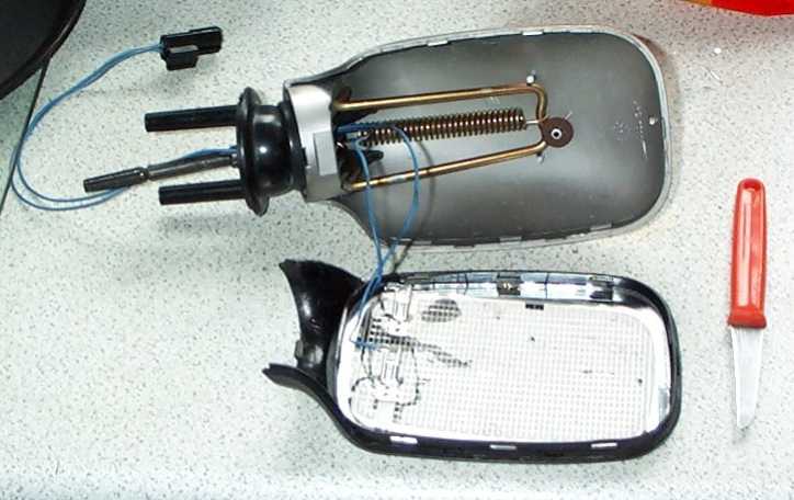
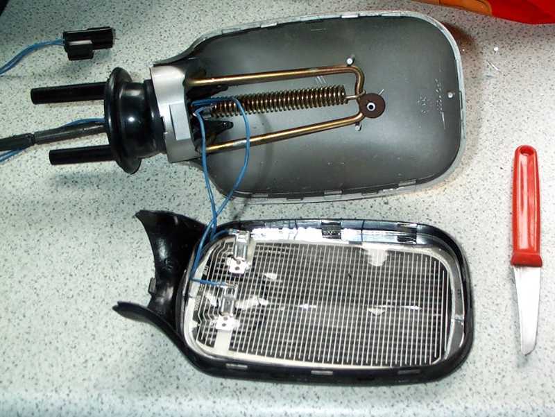
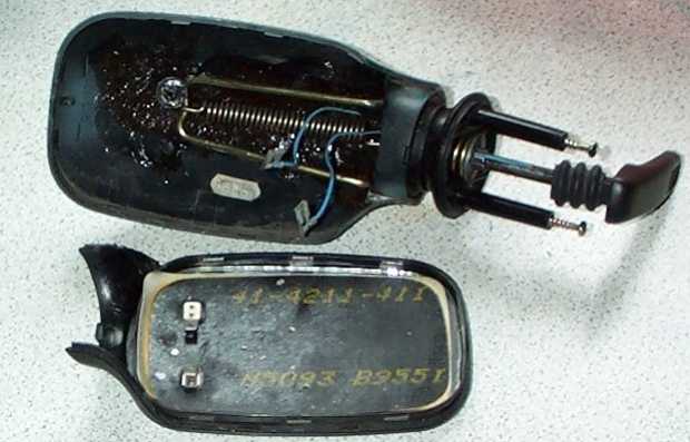


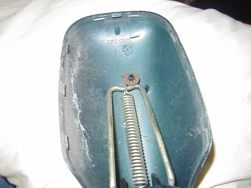
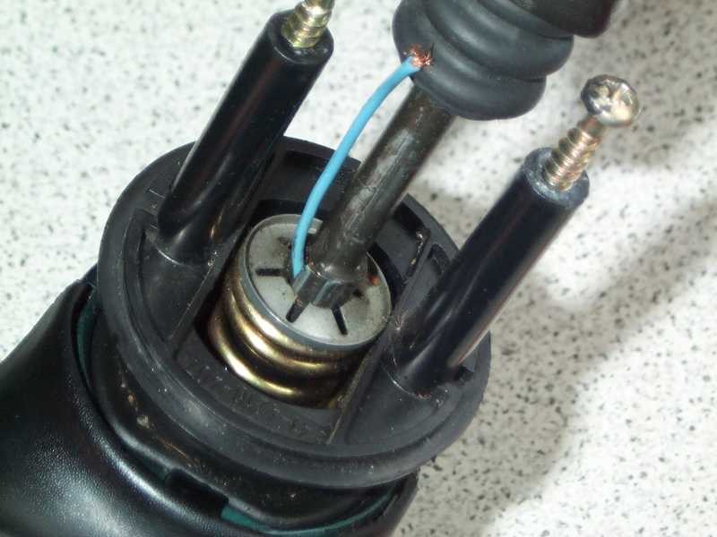
This spring force is responsible for keeping the mirror adjustment in place finally.
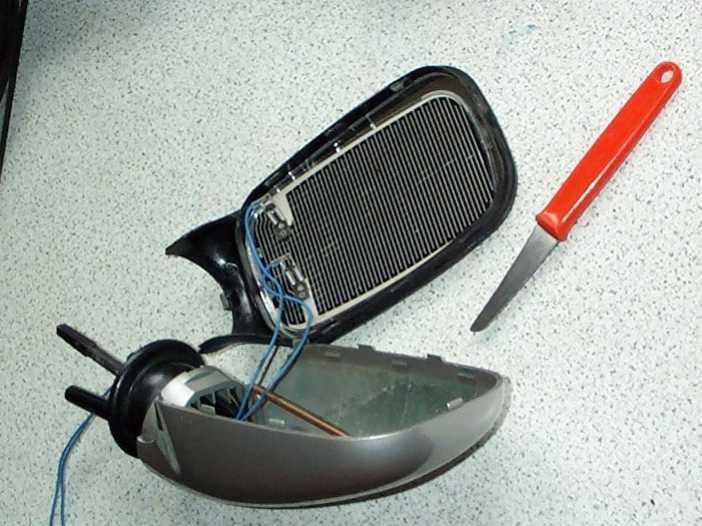
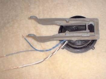
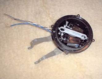
Motor assy of the electric mirror
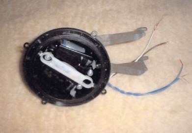
2 motors inside
I had the same problem when I updated my mirrors in the summer, in the end I made my own wiring loom up.
The wires from the mirror's are:
Both Black-Heated mirror element
Brown+White-Vertical Axis
Blue+Grey-Horizontal Axis
Terminals on back of switch numbered 1-7
1- Vertical axis N/S
2- Vertical axis O/S
3- Common (ie return from both axis/mirror )
4- Feed supply to switch from fusebox
5- Horizontal axis O/S
6- Earth from switch
7- Horizontal axis N/S