changing the K-Engine Head Gasket at an MGF
From: Roger Parker Tamworth ------@virgin.net on 22 July 2001 at 01:18:39 (UK time)Yesterday I changed the head of another F for a modified one. No gasket failures to consider but the work is similar.
However before delving into this there are heated words based on perhaps a lack of knowledge and understanding. There is an issue with gasket failures on MGF, but this is clearly more prevelant on cars built in the 1997/8 period. These cars also seem to be able to suffer repeat failures.
I have noted a marked reduction in the incidence of failure in cars after 1999. Why? Well there are a raft of changes to the engines by those who have been sitting on their bums!! There is a valid point in terms of support for those who have cars in this succeptable period and suffer from failure.
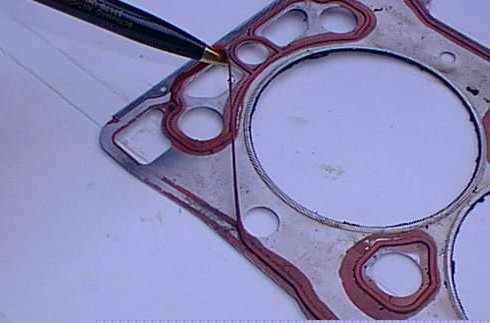
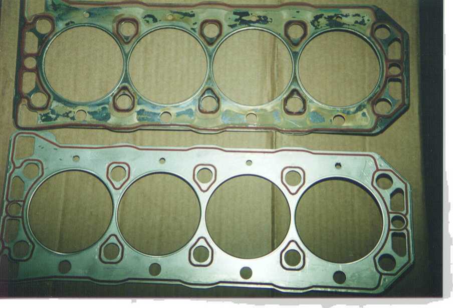
Yesterdays change was on an MPi and retained the plastic manifold. I noted that the head gasket set was sourced direct from Rover central parts store and it contained a gasket with some features I have not seen before. The stamped in part number was also different to the ones I have viewed before, even recently. This gasket had additional blocks of the sealant material at the front end of the gasket in the general area of the breather passages that allows oil to return to the sump.
I also used new steel dowels to locate the head to block, which is creating a far more rigid connection than can be achieved by the original plastic dowels. The cam belt was also changed.
I find that doing this job on an F takes about 50% longer than a FWD car simply from the restricted position of the engine. It isn't actually difficult to do, it's just bloody awkward to do certain aspects.
I have removed heads with inlet manifolds before but on balance I find it easier to remove the manifold and leave that in the engine bay. The slightly difficult positioning of the manifold to head nuts (7 off, 4 underneath) is offset by not needing to remove electrical connections from the engine managment components on the manifold nor break into the fuel system and have a degree of spillage, however careful you are.
If you are removing the head to either change or just for a gasket change then the lump, although much lighter than many heads, is far easier to man handle without manifold.
BTW remove the header tank (2 x 8mm headed bolts and lift out of engagement with the lower rubber locator and then you can get at the lower hose) and also remove the dipstick/filler abortion. One bolt fixing to the inlet manifold, watch the spacer between the assembly and manifold, then reach under the assembly where it attaches to the dipstick steel pipe and lift the collar and it will slide up and clear of the engine bay. Revel in the extra room this gives!!
Always check that the jiggle valve in the cambelt end of the engine is free as this makes the coolant refil and bleed procedure so much easier. I usually give it a little WD40 or similar to help it along.
Positioning the engine prior to removal of the belt is a doddle and there are plenty of marks. However note that the cam wheels are the same on MPi models for both cams and have identical marks. On one side you will see inlet and a notch in the toothed edge of the wheel and on the opposite side you see exhaust with a similar notch in the wheel edge. Under the locking bolt washer are two slots for the roll pin that provides location on the cam. These too are marked in and ex.
I raise these points to ensure that you are aware that you must fit to the correct holes for the cam your fitting the wheel too. I make a simple mark just top ensure that I refit the same wheel to the same cam. Not vital as long as the correct p[osition is adopted, but it makes for a simpler refit if you do mark each.
Cambelt changes require that the bottom pulley is removed. This is something that I cheat with as I have air tools that makes light work of tight bottom pulley bolts. However this should be lossened long before the head is removed, using whatever long levers and extensions etc suitable for the purpose.
Oh whilst in this area you have to remove the alternatoir drive belt and just to add to the problem there is a very small bolt that sits in the alternator, with it's head sticking into the adjuster bracket. This means that you undo all the nuts and bolts to find that the alternator won't adjust. You have to disengage this hidden bolt first.
Cam belt removal needs the engine mounting on the offside to be removed and the engine supported. The 18mm nuts and bolts for engine mountings are long standing, but still an odd size. The cramped engine bay of the MGF doesn't allow good access for a socket and damn all for any other tool. Use of a long lever is likely!!
To remove the mounting requires that the two main bolts to the engine bracket are removed and the nut onto the body rubber. Then there is the torqur reaction arm that has to be detatched and you thinlk that's it. It is until you try and lift off the bracket!! There is a steel rod cage preventing it from being removed and this is held on by two 13mm headed bolts. Problem is that one is completely hidden! Undo the one you can see and then use a lever to push the road towards the outside of the wheelarch. This gives enough room (just) to slide the bracket up and off.
I suggest that you leave the mount in place (loosened nuts and bolts first though) until the engine through bolts and other high torque bolts are removed or at least loosened and once this bracket is out the engine flops around like a wet blanket.
Actual removal of the bolts holding the wheels to the cams can be somewhat trying!!! The engine position does you no favours here. There is a proper tool for locking the two wheels together (see Haynes)and this can be fabricated reasonably easily. This lockout tool is required whilst you crack the bolts on each wheel. It being a good job that there is a 17mm head on these bolts!!
Cam wheel removal is needed because the belt backing plastic cover is attached to both the head and block and is a continuous run down the exhaust side of the engine. Accidental breakage of this at a seam level with the head face line seems reasonably common and can allow the head to be removed without taking the cam wheels off, however you can't retain the cams in the correct timed positions as the centre two through bolts have their heads slightly covered by casting sections that protrude from each cam. It is vital that your E12 socket has full engagement on the head of each bolt at all times your loosening and ticghtening these. The cams have to be turned more to allow the wide head to pass the cams before you can remove them.
Bolt lengths are critical and have to be checked properly. One aspect not mentioned in this respect is the effect that head skimming has on their function. This isn't mentioned in the workshop manuals since the maximum approved skim is so small it poses no threat. However if a skim of much greater thickness is done then if the bolts are at the end of the permitted tolerance then this skim can undermine the result and thus lead to problems form reduced clamping load, plus perhaps distortion resulting from reduced rigidity of the head face.
Just bear this in mind when the common and uneducated comments come thick and fast that because your head gasket has gone you must have the head skimmed. NOT TRUE. Fact - if you have the head off the car for any reason then use a straight edge and measure for any face distortion and if present measure it and see if it is inside or outside tolerance and act appropriately.
Head bolts are interesting things!! Remove then and store them in the order they came out, so that they return to the same hole and thread. DO NOT DROP them into the holes as you WILL quite easily damage the threads and give your self reasons to cry! Measure them when the head is off by hand tightening them into the hole theu came out off. In use the bolts stretch in the thread area immediately above the section of thread which is inside the receiving thread on the ladder section which is at the bottom of the engine.
Tightening them by hand until you can turn them no more shows where this stretch point starts and where if you were tightening the head down would be leading to no more clamping load on the head, but just additional stretching of the bolt.
At the point where the bolt becomes tight you now measure between the underside of the bolt head to the block and if the measurement is less than 97mm the bolt is serviceable. My own view is that if the measurment is within 3mm of this I renew. I expect to find most bolts with similar lengths. If I find any odd measurements I renew those, and if I find more than 4 odd measurments I renew the lot. 6 plus ukp or not, the job these bolts do is worth the investment.
I mention the 'DON'T TURN THE ENGINE OVER' whilst the head is off again as it is important. That is unless the liners are clamped in place.
If you decide to strip the head then fit ET's fingers and set up the microscope, because if your expereicned at working on A, B and V8 engines then the dimensions of bits and pieces in the K heads will come as a big shock! They are small and need a learnt method to remove and refit efficiently.
When fitting the head back onto the engine, especially when you have replaced the dowels for the steel ones, you will find that the head engagment onto these offers a little resistance. Ensure that the head sits square and ease it on. If you checked that the dowels cleanly fit the holes in the head before refitting the head you will know that it is just a matter of alignement. Take note to follow the procedure for fitting and tightening the through bolts.
Once the head is refitted then you come to the cam belt tightening. Even with the Rover tool for holding the cam wheels in the correct position whilst you fit the belt, I bet most will end up with the belt one tooth out. Especially when a new belt is fitted. This is beacuse the new belt doesn't stretch easily and distortion whilst it has been boxed will take up some of the movement you want.
I get round this by turning the crank back half a tooth. If you look at the crank belt pulley you will have two dimples in the face that are aligned when they straddle a cast in line on the oil pump body. What I do is turn the crank anti clockwise until the right dimple is in line with the oil pump line. (This by just dropping the crank pulley back on and hand turning it.)
Once in this position the belt is fitted as per normal and when engaged and tension added through the tensioner you will be able to turn the crank that half a tooth which will take up the slack properly between the crank and exhaust cam, and you will see the cam marks are sport on. The cam wheels being locked together and being so close to each other means they present no problem and hey presto the cams are correctly timed.
Other hints cover exhaust manifold fit. The heat shield nearest the gearbox has a bracket that is held by the end manifold nut. If you loosely fit the 10mm headed bolt that holds the shield to the bracket so that the thread is just through the captive nut it can be easily moved about to get the exhaust nut in place. The exhaust nut needs the bracket bolt out of the way to gain access to it so doign it this way means that you can easily do both up and not have a fight to locate the small bolt when the braket is tightened byt the exhaust nut.
On the same area those who have had the exhaust rattle cured by dealers fitting the extra steady bracket will find this bracket a real pain in the butt. The reason being that there is no movement of the manifold away from the engine and so you can't remove the exhaust or refit it to the head. When you remove the exhaust nuts often the studs come out as well, and if all come out (as did yesterday, but not all on the previous one) then you will be able to remove, but refitting is a nightmare. Remove the bracket from the engine and refit as a later job. The exhaust studs should be separated from the nuts and fitted to the head before you refit the head to engine.
Everthing else is fairly simple and follows the age old 'refitting is a reversal of the removal procedure' saying! Bleeding the cooling system is not rocket science, but should be done methodically by going round each of the three bleed points and ensuring that air is expelled. I go round at least twice and am only satisfied when I have coolant leaking at the first turn of the bleed plug. (with the expansion cap off)
Also note that operation of the cooling fan is not a clear guide of air in the system. You should really ahve collected all the coolant you can when you drained down the system. By knowing the amount removed, allowing for some loss when the head is lifted, you can judge quite easily when the system should be refilled fully. Any shortfall means an airlock which often have to be coaxed out with a little rapid squeezing of coolant hoses to set up a surge in the system. Running the engine till warm so that the thermostat is open allows the expansion cap to be slowly removed and in turn opening of each blled nipple. You may be surprised to then see and hear air escaping.
Heater output is also a goos guide to airlocks in that circuit. Mediocre heat is common until all locks are out then you can cook toast. Feeling the two main hoses through the spare wheel well area is a good guide to coolant flow in the main circuit. Once hose getting hot and the other not is not a good sign if thew engine has been running more than 10 to 1 minutes. I find that the rapid sqeezing to create a pumping effect held to move things along.
Also note that coolant flow is restricted at idle but holding 1500rpm or more drasitaclly increases the pump flow.
I finally take the car a test drive of about 2 miles using a varied range of revs and not only check levels after but open each blled point as well. For the next few days I also advise coolant level checks first thing in the morning. Overnight cooling and settlement is the most likely time that the lasst remaining air will evacuate the system. Witnessed by a possible drop in coolant level.
Overall I find that taking time and not rushing head removal and refitting
with a new cam belt should occupy about 6 to 8 hours.
Rog
From:
Roger Parker Tamworth -----@virgin.net on 25 July 2001 at 15:15:52 (UK
time)
My post intended to be helpful to any who need it. Feel free to copy it
etc.
I have not done any detailed study of the cars that have suffered gasket failures within my reasonable shpere of influence, but I could see a surge with cars in the 97/98 period. There has been enough time sicne to show a reduction in the incidence for the newer cars and in the interim 97/98 period cars still seem to pop up with problems. The 96 cars still seem to be less affected.
Changes to the engine were ongoign throughout the period, whilst the actual gasket remained unchanged from 1995. I have seen quite a few changes to castings, noting that in several areas there is extra material, often for additional or alternative thread bosses, but apparently more metal that this simple function needs. Certainly rigidity will be affected by some of these changes. I do not have any contacts within Cofton Hackett (engine works) who can elaborate, even if I had I wonder whether they could anyway!
The head change last week used a gasket which I believe is listed under LVB 000230 and may well come with two steel dowels. perhaps someone who has time can double check this and post a confirmation or otherwise. [confirmed part No GUG702613]
Rog
Back to MG Enthusiasts' BBS
Drehmomente
/ Bolt torque
Zylinderkopf / Cylinderhead
Alle Schrauben in 3 Schritten festziehen / Tighten the bolts in three
steps
1. Phase 30 Nm (changed, was 20Nm)
2. Phase 180°
3. Phase180°
Ansaugkrümmer 45 Nm / Inlet manifold
Ventildeckel (Nockenwellendeckel) 9 Nm / Cam cover

turn sequence for cam cover bolts and head bolts
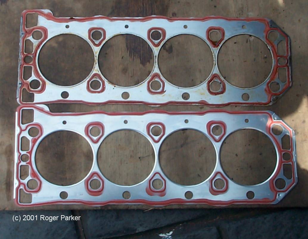
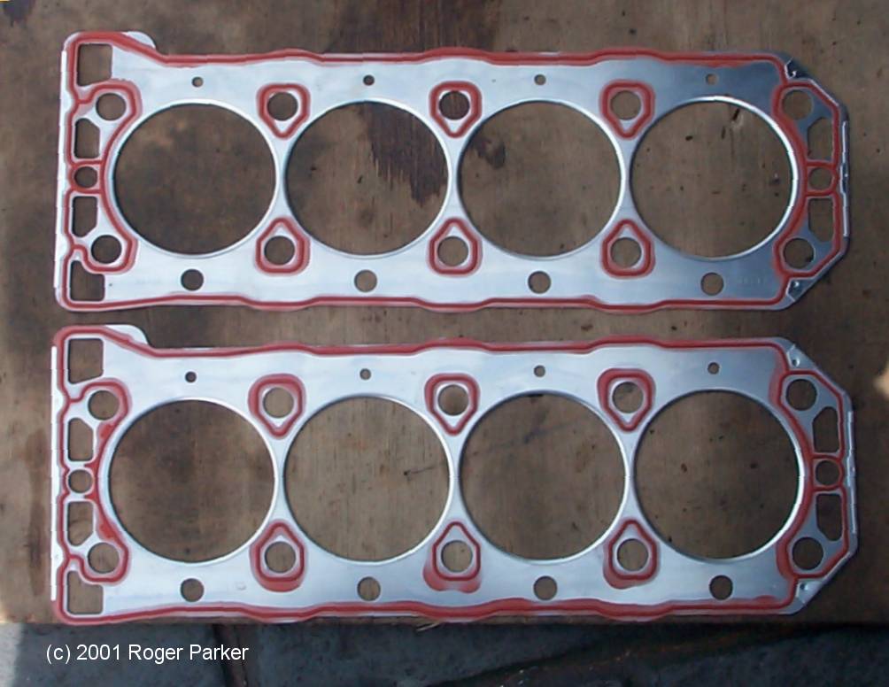
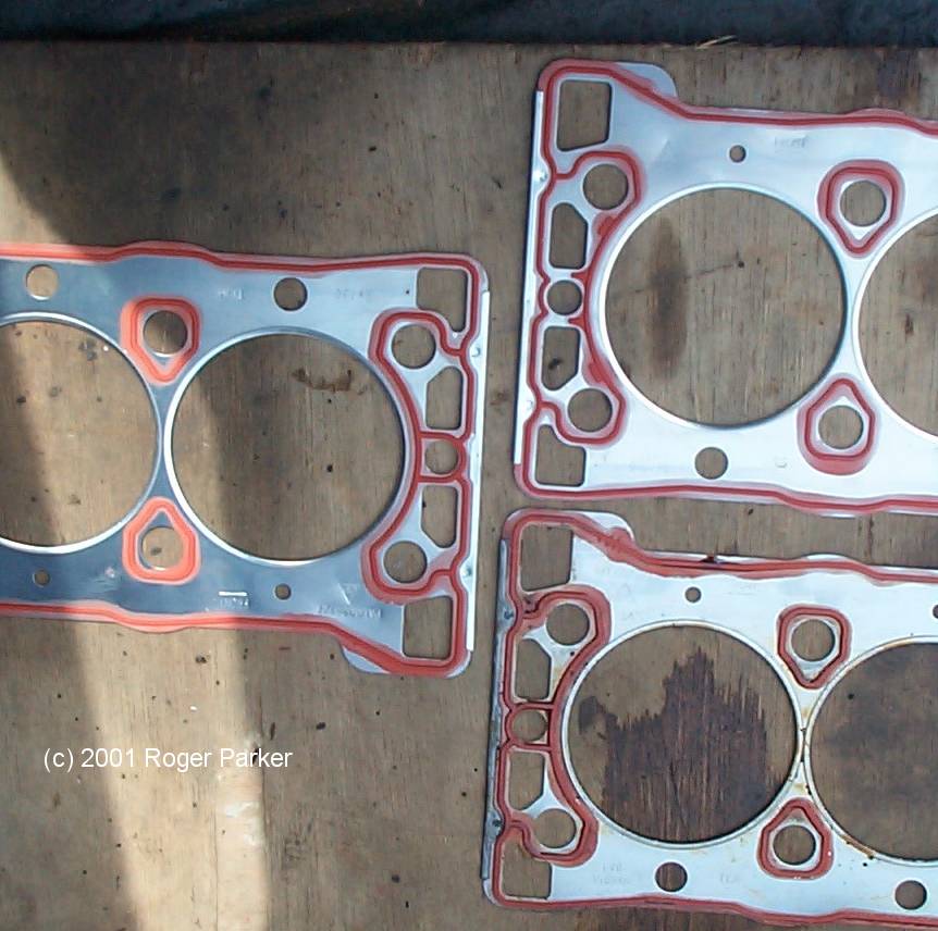
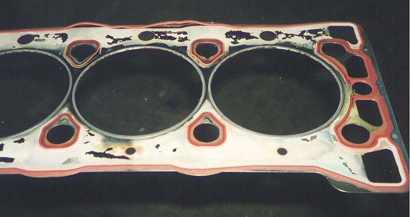
pictures courtesy Roger Parker
picture courtesy Bastian A. (old gasket)
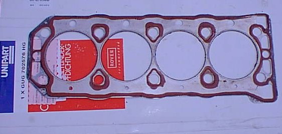
old GUG702576HG
picture courtesy Jon Fredheim
picture courtesy Jon Fredheim
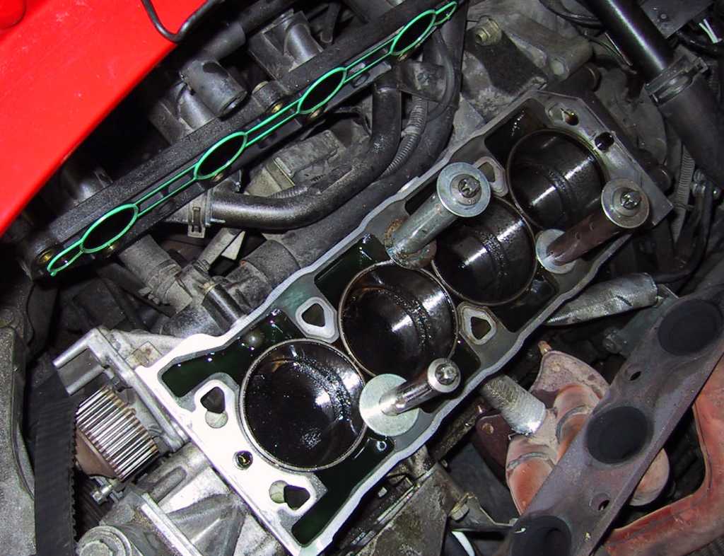
picture courtesy Jon Fredheim

VVC belt
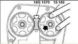
cam wheel tool 18G1570
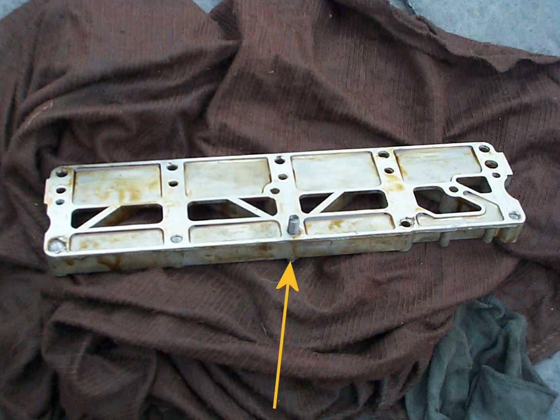
broken bolt in oil rail.
Picture Courtesy Mike Satur (2002)
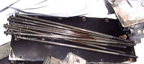
Head Stretch Bolts
Notice:
An official MGR instruction related to the cylinder head gasket is carried
out app July 2001.
An improved gasket with new centering bolts made of metal, instead of
plastic
New head Gasket part No is GUG702784HG. (LVB000320) or Land Rover (LVB100760)
This gasket gets installed by factory already since VIN 1D527784 (March
2001)
stretch bolt torque-
1.Stage 30 Nm (changed, was 20Nm)
2.Stage +180°
3.Stage +180°