Anleitung Karsten
PDF1 und PDF2
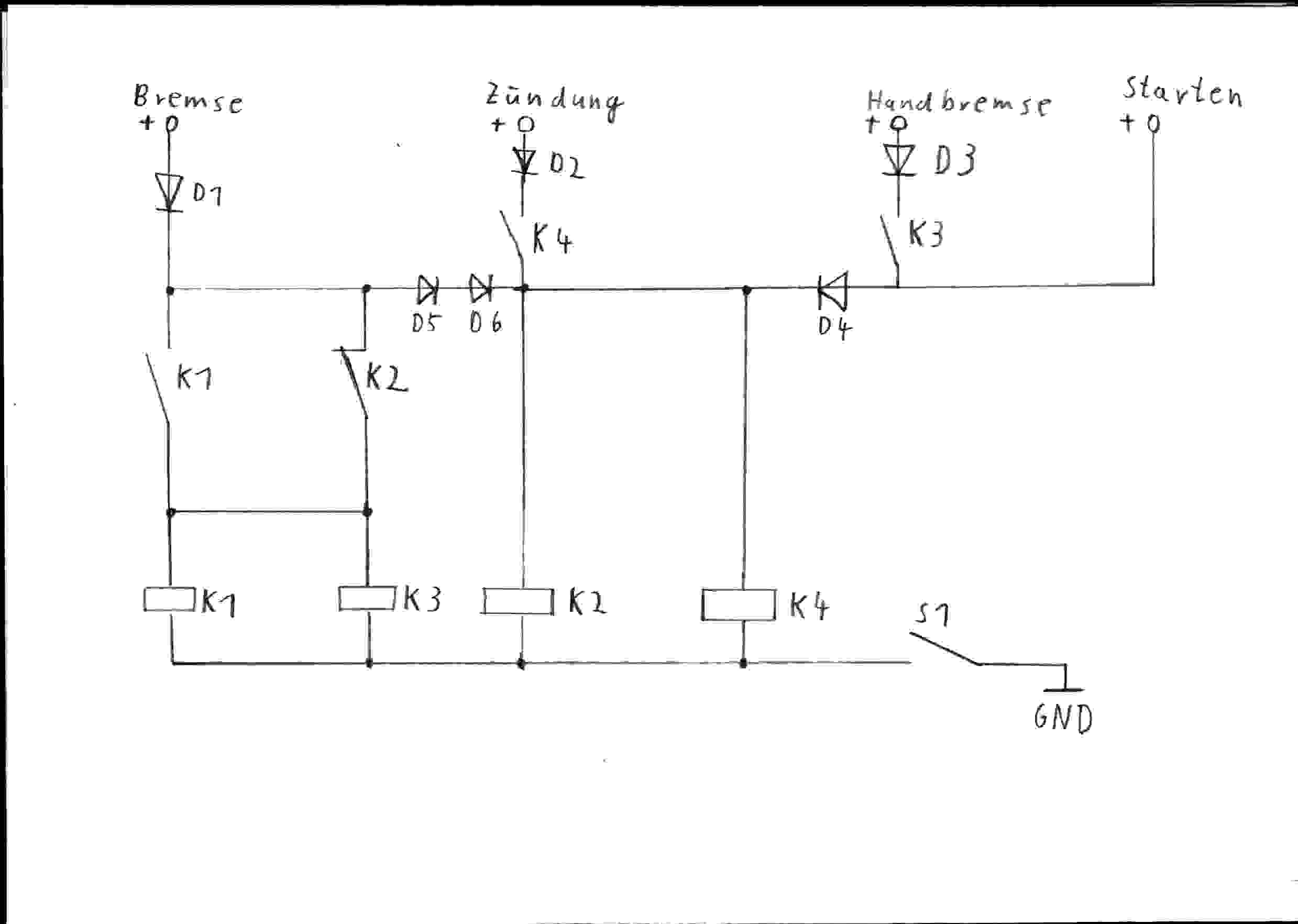
Anschaltung Torsten GIF1
Anschaltung von Steffen
Holz, Starten mit der Bremse
-------------------------------------------------------------
Etwas komplexer:
From: Martin, Guildford
on 02 February 2001 at 11:02:52 (UK time)
Ok then. I've had MS Race Engineering look at the circuit of the F. They
will be looking at producing a kit with instructions now.
If you look at the top left hand corner of the ignition switch page on the F diagrams, you will see the matrix of connections in each switch position. Unfortunately the terminology used in these diagrams has not been constant.
However, we have concluded the following by tracing the circuit:
Matrix labels Ignition
switch labels
Aux = POS2-AUX
BATB = IN1
IG2B = 2B
BATA = IN2
IG1 = 1
IG2A = 2A
CRANK = POS4-CRANK
From tracking this labeling we can now design the circuit for the push button starter.
We need to look at what happens when we move from position 2 to position 3 of the ignition switch; so that the key is still required for the first two positions for the security and switching aspect. When we come to cranking and starting the engine; it will be able to complete this by normal operation of the key switch or by using the starter button.
Basically a single contact press to make is required for the starter button which operates a relay which has three seperate contacts (normally closed) and one seperate contact (normally open).
The starter button
will activate the relay and only when the ignition switch is in position
2 (as per the switch matrix). This then activates the single relay (though
could be a double banked relay depending on availability, costing and
material supplier). The relay will:
1. disconect "WLG" (2B) from the satelite fuse box and hence
the blower.
2. Disconect "Y" (2A)from the circuit.
3.Disconnect "WR" (AUX) from circuit.
4. Connect "WR" (CRANK) in circuit.
The relay will have to be capable of handling the appropriate current
of course; so if there are any DIYers be careful of this.
A recent diagram that was posted on another thread was a bit basic and certainly missed out the requirements I have noted above.
Hope this helps you all for now.


