This pump and its use is only recommended for people who fully understand the suspension system of the car. Each work at the suspension is dangerous without enhanced knowledge of mechanical and hydraulic systems and the efforts of the original design of the car !
IT IS OF UTMOST IMPORTANCE THAT ANY INDIVIDUAL WORKING ON THE HYDRAGAS SYSTEM IS AWARE OF THE HIGH PRESSURE IN THE SYSTEM AND TAKES ALL AND ANY PRECAUTIONS TO AVOID INJURY OR IMPLEMENT FAULTS TO THE HYDRAGAS SYSTEM. NO RESPONSIBILITY IS ACCEPTED FOR ANY SUGGESTIONS MADE HERE. YOU USE THIS INFORMATION AT YOUR OWN RISK WHEN PROPERLY HANDLED THE PROCEDURE IS TOTALLY SAFE AND WILL ALLOW YOU TO MAKE ADJUSTMENTS TO RIDE HEIGHT AND OTHER SUSPENSION WORK EASIER.
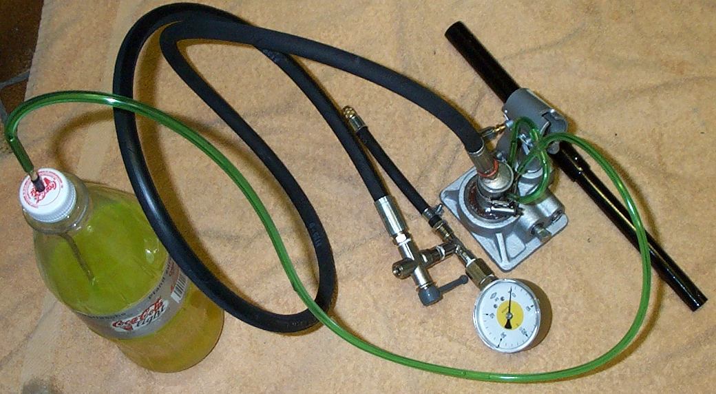
Here it is. I know it looks incredible but it works ! The single parts should cost you not more the about 40 GBP.
Fitting and testing the Pump Unit
PREPARING FOR ASSEMBLY
Each material lists show the parts required to build
this device, and should be just about all that is needed for the task.
Some work still has to be done, such as getting threads on the brake tubes
and inside the cut down pressure tube on hydraulic jack. The design of
your pump depends on availiability of the single parts.
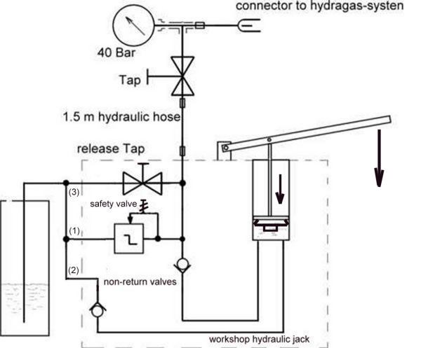
Connector to the hydragas system should be a low loss valve. Means the
flow should be regulated with an extra needle that opens or closes the
schrader valve.
- Empty all oil from the jack and dispose of properly.
- Put jack in a vise (box clamp) and screw off top . This will release the outer tubing and show inner pressure cylinder.
- Only the part of the jack with empty inner tube will be used. The inner tube (diam. approx. 30 mm ) is threaded into base. Remove this inner tube and keep it for later works.
- Now only the base of jack is left. Dismantle all parts and clean with spirit. Watch out for the springs, small steel balls and rubber seals.
- Now there should be no parts left attached to the
cast jack base.
3 small holes (approx. 3 to 4mm diameter) can be seen at the bottom rim in cast part. These are as follows
1- outlet for safety pressure,
2- inlet to pump housing ,
3- return fluid from system when valve on jack is opened.
(Check where the holes lead to by using a small wire)
- Thread these with a inside M4 or M5 thread, as possible. (If the small holes touch already the large thread, then glue the pipes into the holes)
- Thread 3 brake pipe tubes with outside M4 or M5 thread, if possible.
- Clean and join tubes into jack base. Use Loctite, (the best is for hydraulic work) to get it tight and seal.
- The long 30 mm diameter tubing is now cut down to approx. 35 to 40 mm in length and threaded inside with R3/4 inch thread.
- The brass end stop or any other reducing joint is fitted with one extension and same thread as on brass end stop is made inside tubing. (suggestion is R3/4' to R1/8')
- Refit 30 mm diameter tubing in the jack base . Again use Loctite to get it tight.
- Flush with spirit and blow with compressed air to get itclean and dirt free.
- Now all the other parts as the pump spindle and valves etc. can be put back again.
- Connect the 1 m long hydraulic hose and clamp well.
- Connect the plastic hose and t-bars so now all three tubes has one common inlet /outlet, this is the long clear hose to bottle.
- At the other end of hydraulic hose fit a connector with a clamp, tap, T-bar, acetylene meter and finally a connector and clamp to the truck tiyre hose.
- The outer threaded portion of that hose is cut away only the nipple part is used to mate with onboard threaded part on car. (hydra-unit connector)
- Keep the threaded cutaway part .It is threaded with inner M4 and a small M4 screw can be used to plug this. It will be used in testing and when pump is not in use to avoid leakage.
- Now the pump system should be ready for testing.
ATTENTION!
IT IS OF UTMOST IMPORTANCE THAT ANY INDIVIDUAL WORKING ON THE HYDRAGAS SYSTEM IS AWARE OF HIGH PRESSURE IN THE SYSTEM AND TAKE ALL PRECAUTIONS TO AVOID INJURY OR IMPLEMENT FAULTS TO THE HYDRAGAS SYSTEM. NO RESPONSIBILITY IS ACCEPTED FOR ANY SUGGESTIONS MADE HERE. YOU USE THIS INFORMATION AT YOUR OWN RISK
WHEN PROPERLY HANDLED THE PROCEDURE IS TOTALLY SAFE AND WILL ALLOW YOU TO MAKE ADJUSTMENTS TO RIDE HEIGHT AND OTHER SUSPENSION WORK EASIER.
TESTING
- Fill system with spirit. I used 'Carburettor Spirit' - the one to use in winter to get rid of water in fuel system. Easily obtainable in 0,5 L bottles at any petrol station.
- Fill the pump housing and close the valve at the jack base.
- Pump steady and let spirit re-circulate into the bottle. After some strokes all air should be out of system .
- Now close the nipple at the outlet with the cutaway brass part with the threaded plug.
- Pump slowly and see pressure rising .
- When it reaches 35 Bar, open up the safety valve with a screwdriver and adjust it to 'slightly before leaking'.
- Pump again and check that it opens at approx . 35 to 40 Bar.
- Close the tap handle at the meter end.
- Leave the system with pressure for a minute.
- Check for leaks .
- Open tap and some drop in pressure will be seen.
- Now release the pressure slowly by opening the valve at jack base. Pressure should drop to zero.
- Note any air coming out and repeat the above a few times.
- The system check is now complete and if all is well
empty the spirit and refilled with the green stuff.
Go to [Building] [Using] [L-0 Pump Unit] [L-1] [L-2] [L-3] [L-4] [Technical Homepage]
(c) Carl G.B. 16.11.99 edited by Dieter Koennecke and spell checked by Tony Smith